Sponsored


Upper ball joint nut and tie rod are 46 lb.ft. The axle nut is 221 lb.ft


- First Name
- Brian
- Joined
- Jul 17, 2020
- Threads
- 6
- Messages
- 571
- Reaction score
- 808
- Location
- Northern Colorado
- Vehicle(s)
- 1966 Bronco, 2013 F-150
- Your Bronco Model
- Badlands
I believe so. the bearings are a sealed/preloaded cartridge.Safe to say the bearing preload isn't provided by the axle stub nut?
I plan on doing a perch collar lift kit today and I'm having trouble finding torque specs too. I need front lower control arm inner bolts (next to frame) front and rear lower strut bolts. I've dug around on here and found the rest I think. If anyone has the top strut mount specs too. Any help would be appreciated.
Sponsored
- First Name
- Phil
- Joined
- Jul 21, 2020
- Threads
- 41
- Messages
- 4,289
- Reaction score
- 14,222
- Location
- IN
- Website
- www.ruxerparts.com
- Vehicle(s)
- Fords
- Your Bronco Model
- Badlands
Lower Arm
Special Tool(s) / General Equipment
Removal
NOTICE: Suspension fasteners are critical parts that affect the performance of vital components and systems. Failure of these fasteners may result in major service expense. Use the same or equivalent parts if replacement is necessary. Do not use a replacement part of lesser quality or substitute design. Tighten fasteners as specified.
Installation
NOTICE: Tighten the suspension bushing fasteners with the suspension raised by a jack to curb height or with the weight of the vehicle resting on the wheels and tires. Otherwise, damage to the bushings may occur.
Special Tool(s) / General Equipment

| 204-592 Separator, Lower Arm Ball Joint TKIT-2006C-FFMFLM TKIT-2006C-LM TKIT-2006C-ROW |

| 205-D070 (D93P-1175-B) Remover, Front Wheel Hub |
| Vehicle/Axle Stands |
NOTICE: Suspension fasteners are critical parts that affect the performance of vital components and systems. Failure of these fasteners may result in major service expense. Use the same or equivalent parts if replacement is necessary. Do not use a replacement part of lesser quality or substitute design. Tighten fasteners as specified.
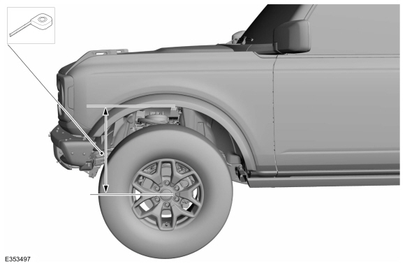
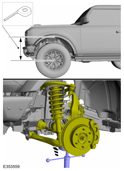
- Measure and record the distance from the center of the hub to the lip of the fender with the vehicle in a level, static ground position (curb height).
|
|


- Remove the wheel and tire.
Refer to: Wheel and Tire (204-04A Wheels and Tires, Removal and Installation).
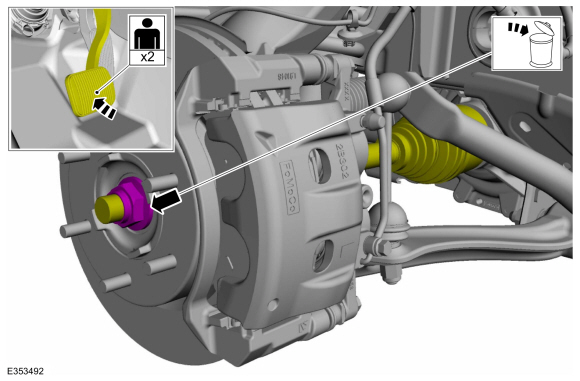
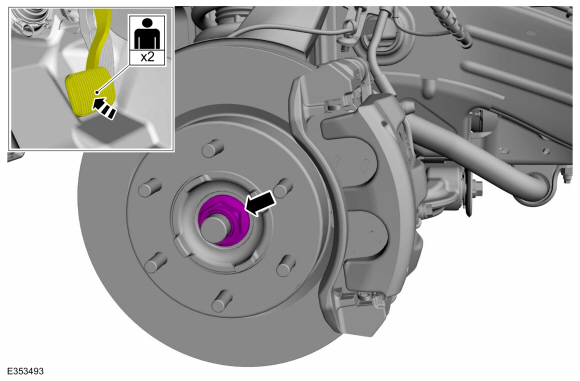
- NOTE: This step requires the aid of another technician.
NOTE: Apply the brake to prevent the halfshaft from rotating while loosening the wheel hub nut.
Remove and discard the wheel hub nut.
|
|
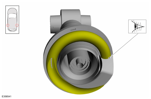
- Using the special tool, press the halfshaft from the front wheel bearing and hub and support the halfshaft using mechanic's wire.
Use Special Service Tool: 205-D070 (D93P-1175-B) Remover, Front Wheel Hub.
|
|
- Remove and discard the shock absorber assembly lower nuts.
|
|
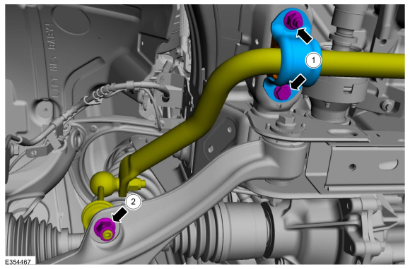
- NOTE: The stabilizer bar links are designed with low friction ball joints that have a low breakaway torque.
NOTE: Use the hex-holding feature to prevent the stud from turning while removing the nuts.
Remove and discard the stabilizer bar link lower nut.

|
|
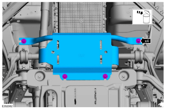
- If equipped.
Remove and discard the bolts and remove the stabilizer bar undershield.
|
|
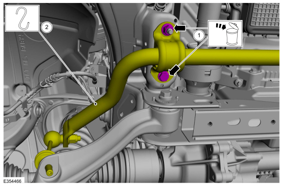
- NOTE: Note the position of each component before removal.
- Remove and discard the front stabilizer bar assembly nut and bolt.
- Position aside the front stabilizer bar assembly and support the front stabilizer bar assembly using mechanic's wire.
|
|
- NOTICE: Never allow the knuckle to hang from the upper and lower control arms or damage to the ball joints can occur.
NOTE: Take care not to damage coating on suspension components.
Support the wheel knuckle assembly using mechanic's wire.

|
|
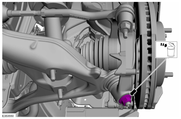
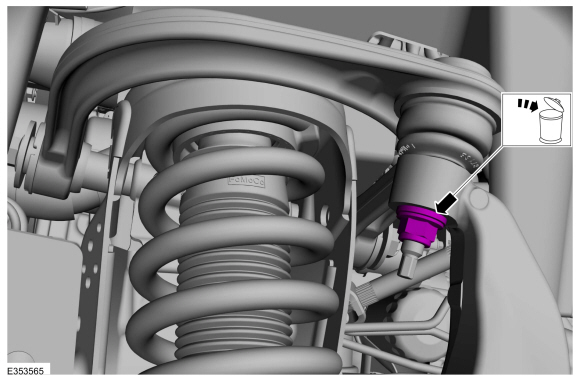
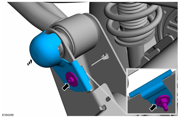
- NOTE: Use the hex-holding feature to prevent the stud from turning while removing the nut.
Remove and discard the lower ball joint nut.
|
|
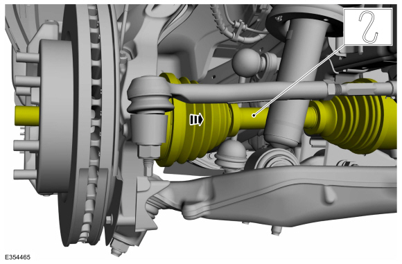
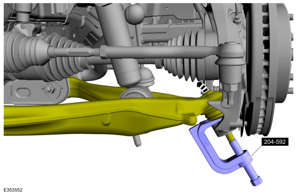
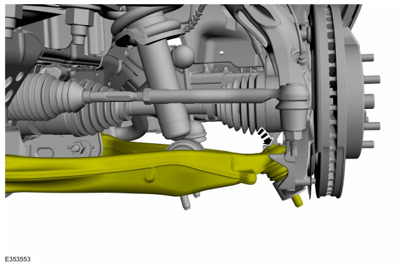
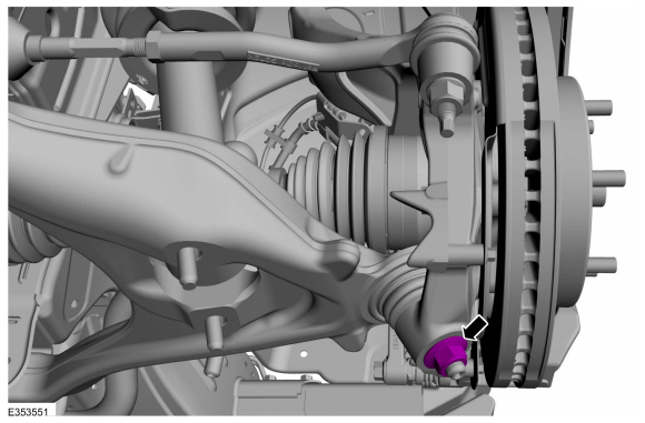
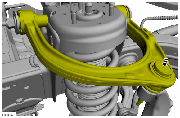
- NOTICE: Do not use a prying device or separator fork between the ball joint and the wheel knuckle. Damage to the ball joint or ball joint seal may result.
NOTICE: Use care when releasing the lower arm and wheel knuckle into the resting position or damage to the ball joint seal may occur.
NOTICE: Do not damage the ball joint boot while installing the special tool.
Separate the lower ball joint from the wheel knuckle.
Use Special Service Tool: 204-592 Separator, Lower Arm Ball Joint.
|
|
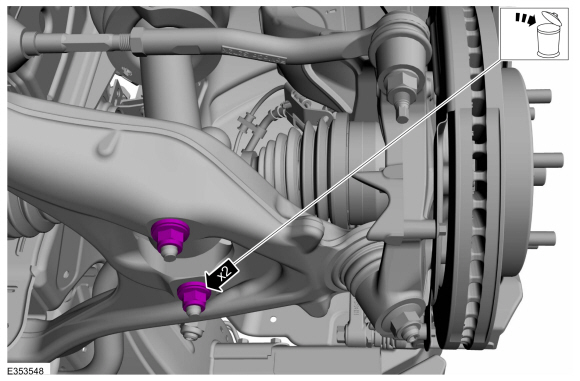
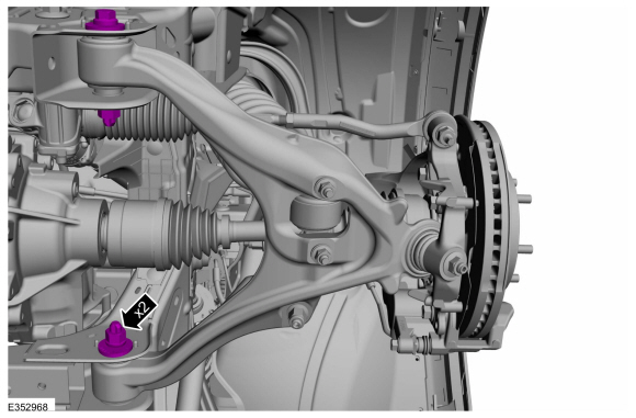
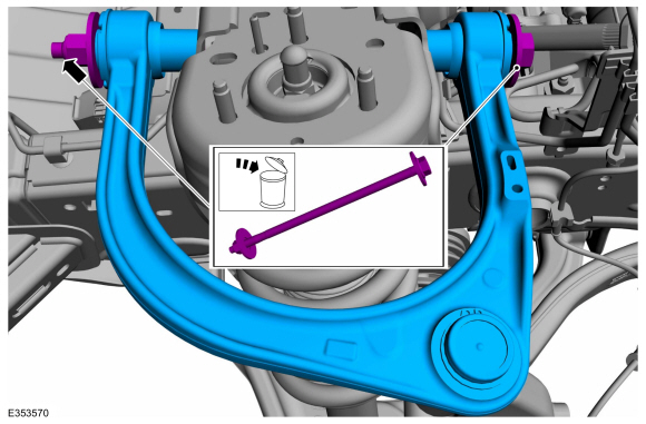
- Remove and discard the lower arm bolts, nuts and washers and remove the lower arm.
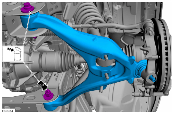
|
|
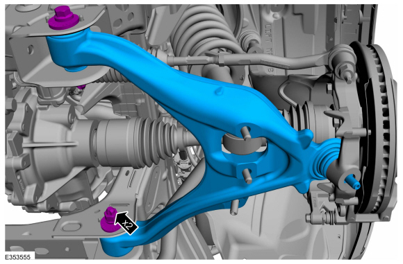
NOTICE: Tighten the suspension bushing fasteners with the suspension raised by a jack to curb height or with the weight of the vehicle resting on the wheels and tires. Otherwise, damage to the bushings may occur.
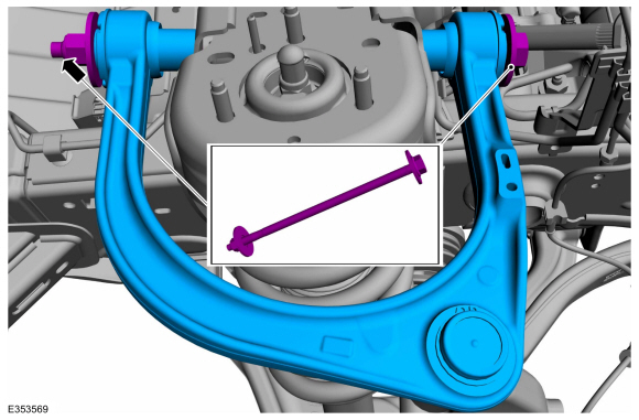
- NOTE: Only tighten the nuts and bolts finger tight at this stage.
Install the lower arm and install the new lower arm bolts, nuts and washers.
|
|
- NOTE: Make sure that the component is installed to the position noted before removal.
- Position the front stabilizer bar assembly and install the new stabilizer bar bracket nut and bolt.
Torque: 66 lb.ft (90 Nm)
- Position the front stabilizer bar assembly and install the new stabilizer bar bracket nut and bolt.
- NOTE: The stabilizer bar links are designed with low friction ball joints that have a low breakaway torque.
NOTE: Use the hex-holding feature to prevent the stud from turning while removing the nuts.
Position the stabilizer bar link and install the new stabilizer bar link lower nut.
Torque: 122 lb.ft (165 Nm)
- NOTE: The stabilizer bar links are designed with low friction ball joints that have a low breakaway torque.
|
|
- If removed.
Install the stabilizer bar undershield and install the new stabilizer bar undershield bolts.
Torque: 26 lb.ft (35 Nm)
|
|
|
- Attach the lower ball joint to the wheel knuckle.
|
|
- NOTE: Use the hex-holding feature to prevent the stud from turning while installing the nut.
Install the new lower ball joint nut.
Torque: 85 lb.ft (115 Nm)
|
|
- With old hub nut pull the halfshaft into hub and discard the old wheel hub nut.

|
|
- NOTICE: Install and tighten the new wheel hub nut to specification in a continuous rotation. Always install a new wheel hub nut after loosening or when not tightened to specification in a continuous rotation or damage to the components may occur.
NOTE: This step requires the aid of another technician.
NOTE: Apply the brake to keep the halfshaft from rotating.
While an assistant applies the brake, install the new halfshaft nut.
Torque: 221 lb.ft (300 Nm)
|
|
- Install the new shock absorber assembly lower nuts.
Torque: 66 lb.ft (90 Nm)

|
|
- Use a suitable jack to raise the suspension until the distance between the center of the hub and the lip of the fender is equal to the measurement taken during removal (curb height).
Use the General Equipment: Vehicle/Axle Stands
|
|
- NOTICE: Tighten the suspension bushing fasteners with the suspension raised by a jack to curb height or with the weight of the vehicle resting on the wheels and tires. Otherwise, damage to the bushings may occur.
Tighten the new lower arm bolts and nuts.
Torque: 210 lb.ft (285 Nm)
|
|
- Install the wheel and tire.
Refer to: Wheel and Tire (204-04A Wheels and Tires, Removal and Installation).
- Check and if necessary adjust front camber and caster.
Refer to: Front Camber and Caster Adjustment (204-00 Suspension System - General Information, General Procedures).
- Check and if necessary adjust front toe.
Refer to: Front Toe Adjustment (204-00 Suspension System - General Information, General Procedures).
- First Name
- Phil
- Joined
- Jul 21, 2020
- Threads
- 41
- Messages
- 4,289
- Reaction score
- 14,222
- Location
- IN
- Website
- www.ruxerparts.com
- Vehicle(s)
- Fords
- Your Bronco Model
- Badlands
Upper Arm
Special Tool(s) / General Equipment
Removal
NOTICE: Suspension fasteners are critical parts that affect the performance of vital components and systems. Failure of these fasteners may result in major service expense. Use the same or equivalent parts if replacement is necessary. Do not use a replacement part of lesser quality or substitute design. Tighten fasteners as specified.
NOTE: Removal steps in this procedure may contain installation details.
Installation
NOTICE: Tighten the suspension bushing fasteners with the suspension raised by a jack to curb height or with the weight of the vehicle resting on the wheels and tires. Otherwise, damage to the bushings may occur.
Special Tool(s) / General Equipment
|
| 204-592 Separator, Lower Arm Ball Joint TKIT-2006C-FFMFLM TKIT-2006C-LM TKIT-2006C-ROW |
| Vehicle/Axle Stands |
NOTICE: Suspension fasteners are critical parts that affect the performance of vital components and systems. Failure of these fasteners may result in major service expense. Use the same or equivalent parts if replacement is necessary. Do not use a replacement part of lesser quality or substitute design. Tighten fasteners as specified.
NOTE: Removal steps in this procedure may contain installation details.
- Measure and record the distance from the center of the hub to the lip of the fender with the vehicle in a level, static ground position (curb height).
|
|
|
- Remove the wheel and tire.
Refer to: Wheel and Tire (204-04A Wheels and Tires, Removal and Installation).
- NOTICE: The suspension height sensors must be disconnected prior to servicing suspension components. Damage to the suspension height sensors and/or the vehicle dynamic suspension system may occur.
If equipped.
Remove the height sensor arm bracket bolt and position aside the bracket.

|
|
- NOTE: RH side only.
Remove the upper arm shield nut and shield.

|
|
- NOTICE: Never allow the knuckle to hang from the upper and lower control arms or damage to the ball joints can occur.
NOTE: Take care not to damage coating on suspension components.
Support the wheel knuckle assembly using mechanic's wire.

|
|
- NOTE: Use the hex-holding feature to prevent the stud from turning while removing the nut.
Remove and discard the upper ball joint nut.
|
|
- NOTE: Be sure not to damage the ball joint boot when installing the Ball Joint Separator.
Separate the upper ball joint from the wheel knuckle.
Use Special Service Tool: 204-592 Separator, Lower Arm Ball Joint.

|
|
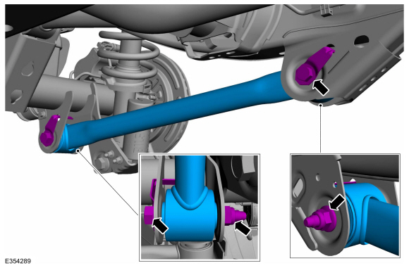
- Remove and discard the upper arm bolt and nut and remove the upper arm.
|
|
NOTICE: Tighten the suspension bushing fasteners with the suspension raised by a jack to curb height or with the weight of the vehicle resting on the wheels and tires. Otherwise, damage to the bushings may occur.
- NOTE: Only tighten the nut and bolt finger tight at this stage.
Position the upper arm and install the new upper arm bolt and nut.
|
|
- Attach the upper ball joint to the wheel knuckle.
|
|
- NOTE: Use the hex-holding feature to prevent the stud from turning while installing the nut.
Install the new upper ball joint nut.
Torque: 46 lb.ft (63 Nm)
|
|
- Use a suitable jack to raise the suspension until the distance between the center of the hub and the lip of the fender is equal to the measurement taken during removal (curb height).
Use the General Equipment: Vehicle/Axle Stands
|
|
|
- NOTICE: Tighten the suspension bushing fasteners with the suspension raised by a jack to curb height or with the weight of the vehicle resting on the wheels and tires. Otherwise, damage to the bushings may occur.
Tighten the new upper arm bolt and nut.
Torque: 122 lb.ft (165 Nm)

|
|
- NOTE: RH side only.
Install the upper arm shield and tighten the shield nut.
Torque: 80 lb.in (9 Nm)
|
|
|
- If equipped.
Position the height sensor arm bracket and install the bolt.
Torque: 53 lb.in (6 Nm)
|
|
|
- Install the wheel and tire.
Refer to: Wheel and Tire (204-04A Wheels and Tires, Removal and Installation).
- If equipped.
- Calibrate the suspension height sensor. Connect the scan tool and carry out the Ride Height Calibration routine. Follow the scan tool directions.
- Check and if necessary adjust front camber.
Refer to: Front Camber and Caster Adjustment (204-00 Suspension System - General Information, General Procedures).
- Check and if necessary adjust front toe.
Refer to: Front Toe Adjustment (204-00 Suspension System - General Information, General Procedures).
- First Name
- Phil
- Joined
- Jul 21, 2020
- Threads
- 41
- Messages
- 4,289
- Reaction score
- 14,222
- Location
- IN
- Website
- www.ruxerparts.com
- Vehicle(s)
- Fords
- Your Bronco Model
- Badlands
Damn, all of those nuts/bolts are single use? or is that just a standard practice for Ford service?
If single use, i guess its time to make another parts run....
If single use, i guess its time to make another parts run....
Awesome! Thanks @flip ! This should definitely be added as a sticky in this section of the forum as seen here many people are starting to look for this stuff. Also any help with the rear?
Sponsored
- First Name
- Phil
- Joined
- Jul 21, 2020
- Threads
- 41
- Messages
- 4,289
- Reaction score
- 14,222
- Location
- IN
- Website
- www.ruxerparts.com
- Vehicle(s)
- Fords
- Your Bronco Model
- Badlands
Lower Arm
Special Tool(s) / General Equipment
Removal
NOTICE: Suspension fasteners are critical parts that affect the performance of vital components and systems. Failure of these fasteners may result in major service expense. Use the same or equivalent parts if replacement is necessary. Do not use a replacement part of lesser quality or substitute design. Tighten fasteners as specified.
NOTE: Removal steps in this procedure may contain installation details.
Installation
NOTICE: Tighten the suspension bushing fasteners with the suspension raised by a jack to curb height or with the weight of the vehicle resting on the wheels and tires. Otherwise, damage to the bushings may occur.
Special Tool(s) / General Equipment
| Vehicle/Axle Stands |
NOTICE: Suspension fasteners are critical parts that affect the performance of vital components and systems. Failure of these fasteners may result in major service expense. Use the same or equivalent parts if replacement is necessary. Do not use a replacement part of lesser quality or substitute design. Tighten fasteners as specified.
NOTE: Removal steps in this procedure may contain installation details.
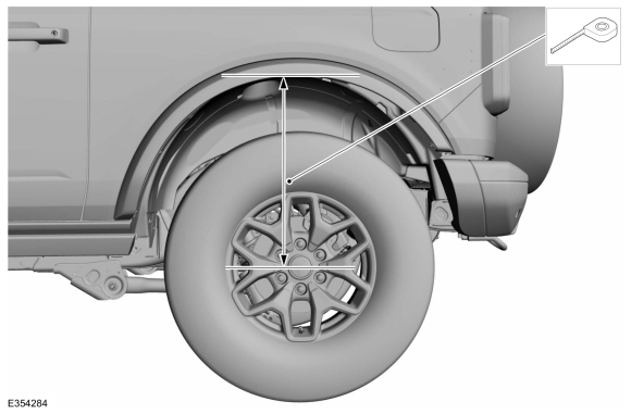
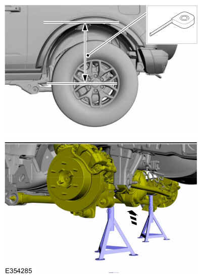
- Measure and record the distance from the center of the hub to the lip of the rear fender with the vehicle in a level, static ground position (curb height).
|
|
- With the vehicle in NEUTRAL, position it on a hoist.
Refer to: Jacking and Lifting (100-02 Jacking and Lifting, Description and Operation).
- NOTE: This step is only necessary when removal and installing a RH side component.
Remove the fuel tank.
Refer to: Fuel Tank (310-01A Fuel Tank and Lines - 2.3L EcoBoost (199kW/270PS), Removal and Installation).
Refer to: Fuel Tank (310-01B Fuel Tank and Lines - 2.7L EcoBoost (238kW/324PS), Removal and Installation).
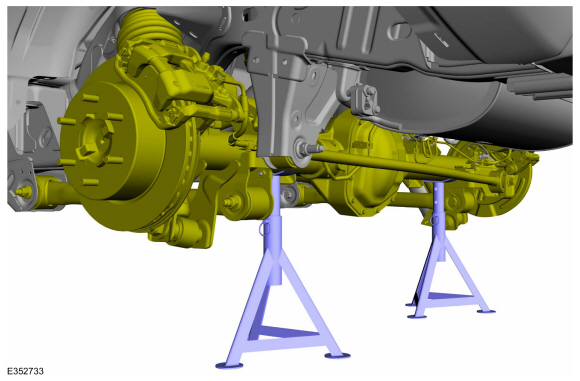
- NOTICE: Do not position the jack on the front control arm or rear control arm on any vehicle. Damage to control arms may occur.
NOTICE: Make sure that the jack insulator pads are correctly positioned to prevent direct contact with other components
Support the rear suspension.
Use the General Equipment: Vehicle/Axle Stands
|
|
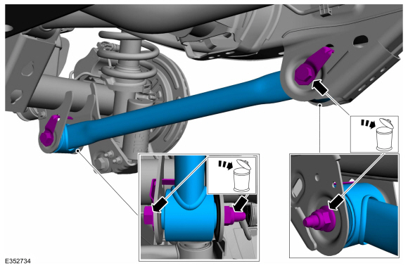
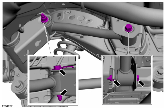
- NOTE: Note the position of the component before removal.
Remove and discard the lower arm bolts and nuts and remove the lower arm.
|
|
NOTICE: Tighten the suspension bushing fasteners with the suspension raised by a jack to curb height or with the weight of the vehicle resting on the wheels and tires. Otherwise, damage to the bushings may occur.
- NOTE: Make sure that the component is installed to the position noted before removal.
NOTE: Only tighten the nuts and bolts finger tight at this stage.
Position the lower arm and install the lower arm new bolts and nuts.
|
|
- NOTICE: Make sure that the jack insulator pads are correctly positioned to prevent direct contact with other components.
Use a suitable jack to raise the suspension until the distance between the center of the hub and the lip of the rear fender is equal to the measurement taken during removal (raise the suspension to curb height).
Use the General Equipment: Vehicle/Axle Stands
|
|
- NOTICE: Tighten the suspension bushing fasteners with the suspension raised by a jack to curb height or with the weight of the vehicle resting on the wheels and tires. Otherwise, damage to the bushings may occur.
Tighten the lower arm bolts and nuts.
Torque: 159 lb.ft (215 Nm)
|
|
- NOTE: This step is only necessary when removal and installing a RH side component.
Install the fuel tank.
- First Name
- Phil
- Joined
- Jul 21, 2020
- Threads
- 41
- Messages
- 4,289
- Reaction score
- 14,222
- Location
- IN
- Website
- www.ruxerparts.com
- Vehicle(s)
- Fords
- Your Bronco Model
- Badlands
Upper Arm
Special Tool(s) / General Equipment
Removal
NOTICE: Suspension fasteners are critical parts that affect the performance of vital components and systems. Failure of these fasteners may result in major service expense. Use the same or equivalent parts if replacement is necessary. Do not use a replacement part of lesser quality or substitute design. Tighten fasteners as specified.
NOTE: Removal steps in this procedure may contain installation details.
Installation
NOTICE: Tighten the suspension bushing fasteners with the suspension raised by a jack to curb height or with the weight of the vehicle resting on the wheels and tires. Otherwise, damage to the bushings may occur.
Special Tool(s) / General Equipment
| Vehicle/Axle Stands |
NOTICE: Suspension fasteners are critical parts that affect the performance of vital components and systems. Failure of these fasteners may result in major service expense. Use the same or equivalent parts if replacement is necessary. Do not use a replacement part of lesser quality or substitute design. Tighten fasteners as specified.
NOTE: Removal steps in this procedure may contain installation details.
- Measure and record the distance from the center of the hub to the lip of the rear fender with the vehicle in a level, static ground position (curb height).
|
|
|
- With the vehicle in NEUTRAL, position it on a hoist.
Refer to: Jacking and Lifting (100-02 Jacking and Lifting, Description and Operation).
- NOTE: This step is only necessary when removal and installing a RH side component.
Remove the fuel tank.
Refer to: Fuel Tank (310-01A Fuel Tank and Lines - 2.3L EcoBoost (199kW/270PS), Removal and Installation).
Refer to: Fuel Tank (310-01B Fuel Tank and Lines - 2.7L EcoBoost (238kW/324PS), Removal and Installation).
- NOTE: This step is only necessary when removal and installing a RH side component.
Remove the fuel tank shield fastner and remove the shield.

|
|
- NOTICE: Make sure that the jack insulator pads are correctly positioned to prevent direct contact with other components
Support the rear suspension.
Use the General Equipment: Vehicle/Axle Stands
|
|
|
- NOTE: Note the position of the component before removal.
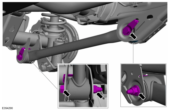
Remove and discard the upper arm bolts and nuts and remove the upper arm.

|
|
NOTICE: Tighten the suspension bushing fasteners with the suspension raised by a jack to curb height or with the weight of the vehicle resting on the wheels and tires. Otherwise, damage to the bushings may occur.
- NOTE: Make sure that the component is installed to the position noted before removal.
NOTE: Only tighten the nuts and bolts finger tight at this stage.
Position the upper arm and install the upper arm new bolts and nuts.

|
|
- NOTICE: Make sure that the jack insulator pads are correctly positioned to prevent direct contact with other components.
Use a suitable jack to raise the suspension until the distance between the center of the hub and the lip of the rear fender is equal to the measurement taken during removal (raise the suspension to curb height).
Use the General Equipment: Vehicle/Axle Stands
|
|
|
- NOTICE: Tighten the suspension bushing fasteners with the suspension raised by a jack to curb height or with the weight of the vehicle resting on the wheels and tires. Otherwise, damage to the bushings may occur.
Tighten the upper arm bolts and nuts.
Torque: 159 lb.ft (215 Nm)
|
|
- NOTE: This step is only necessary when removal and installing a RH side component.
Position the fuel tank shield and install the shield fastners.
Torque: 97 lb.in (11 Nm)
|
|
- NOTE: This step is only necessary when removal and installing a RH side component.
- First Name
- Phil
- Joined
- Jul 21, 2020
- Threads
- 41
- Messages
- 4,289
- Reaction score
- 14,222
- Location
- IN
- Website
- www.ruxerparts.com
- Vehicle(s)
- Fords
- Your Bronco Model
- Badlands
Shock Absorber and Spring Assembly
Special Tool(s) / General Equipment
Removal
NOTICE: Suspension fasteners are critical parts that affect the performance of vital components and systems. Failure of these fasteners may result in major service expense. Use the same or equivalent parts if replacement is necessary. Do not use a replacement part of lesser quality or substitute design. Tighten fasteners as specified.
NOTE: Removal steps in this procedure may contain installation details.
NOTE: LH side shown, RH side similar.
Installation
NOTE: Do not fully tighten the shock absorber mounting bolts. Tighten the suspension bushing fasteners with the suspension loaded or with the weight of the vehicle resting on the wheels and tires, otherwise incorrect clamp load and bushing damage may occur.
Hitachi - shock absorber and spring assembly.
Bilstein - shock absorber and spring assembly.
All vehicles
Special Tool(s) / General Equipment
| Vehicle/Axle Stands |
NOTICE: Suspension fasteners are critical parts that affect the performance of vital components and systems. Failure of these fasteners may result in major service expense. Use the same or equivalent parts if replacement is necessary. Do not use a replacement part of lesser quality or substitute design. Tighten fasteners as specified.
NOTE: Removal steps in this procedure may contain installation details.
NOTE: LH side shown, RH side similar.
- Remove the wheel and tire.
Refer to: Wheel and Tire (204-04A Wheels and Tires, Removal and Installation).
- Remove the rear quarter panel moulding.
Refer to: Rear Quarter Panel Moulding (501-08 Exterior Trim and Ornamentation, Removal and Installation).
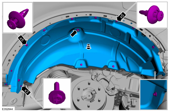
- Detach the retainers and remove the splash shield.
Torque: 18 lb.in (2 Nm)
|
|
- NOTICE: Do not position the jack on the front control arm or rear control arm on any vehicle. Damage to control arms may occur.
NOTICE: Make sure that the jack insulator pads are correctly positioned to prevent direct contact with other components.
With the vehicle on hoist, place axle stands under the rear axle such that the axle stand insulator pads are in contact with the axle.
Use the General Equipment: Vehicle/Axle Stands
|
|
|
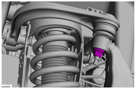
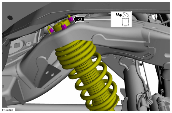
- Remove and discard the rear shock absorber upper nuts.
|
|
- Remove and discard the rear shock absorber lower nut and bolt and remove the shock absorber.
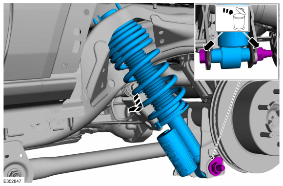
|
|
NOTE: Do not fully tighten the shock absorber mounting bolts. Tighten the suspension bushing fasteners with the suspension loaded or with the weight of the vehicle resting on the wheels and tires, otherwise incorrect clamp load and bushing damage may occur.
Hitachi - shock absorber and spring assembly.
- NOTE: Make sure that the component is installed to the position noted before removal.
On both sides.
Make sure that the spring lower end tip in the shock absorber and spring assembly is facing the RH side of the vehicle.
|
|
- NOTE: Make sure that the component is installed to the position noted before removal.
- Shock absorber reservoir should face forward direction for the vehicle.
- Make sure coil spring lower end tip in the shock assembly must face RH side of the vehicle.

|
|
- NOTE: Make sure a new nut and bolt is installed.
Install the new rear shock absorber and shock absorber lower bolt and nut.
Torque: 350 lb.ft (475 Nm)

|
|
- Install the new rear shock absorber upper nuts.
Torque: 41 lb.ft (55 Nm)

|
|
- To install, reverse the removal procedure.
350 lb-ft is a lot of freaking torque for that lower bolt. Is almost the same torque you get from the 2.3 L engine!

No doubt! Exactly the reason I chose skids for that lower mount that don’t utilize that bolt! You’ll need a torque wrench the size of a flagpole to pull 350 lb-ft! I had heard a 250 lb-ft spec from other sources including an aftermarket manufacturer…350 lb-ft is a lot of freaking torque for that lower bolt. Is almost the same torque you get from the 2.3 L engine!
Sponsored