- Thread starter
- #1
Hopefully this post will help someone with a straight forward description of how I wired in front factory fog lights on a Bronco that has no fogs or front parking sensors.
I have a ’25 Big Bend with no front parking sensors or front fogs. I was looking to swap out the standard plastic bumper with a steel capable bumper. The capable bumper I picked up on FB had the factory fog lights which put me on a quest to wire in the front fogs as close to factory as possible. If you’ve been down this road or researching it, you will know all Broncos have the front fog wires to connector C203. However, only Broncos with front parking sensors or front fog lights have the same wires exiting C203 to connector C192, which then connects to harness 15K867 and to the fogs lights in the bumper. My Big Bend Mid Package did not have any fog light wiring after C203. So, this is what I did:
The first step for me was to wire in a “sub” harness from connector C203 to a tab where connector C192 attaches in the front of driver’s side fender under the headlight. What I needed:
(2) Ford Terminal DU2Z-14474-DA
Brown 16GA wire (Left power feed)
Yellow/Orange 16GA wire (Right power feed)
Black/Green 16GA wire (Ground)
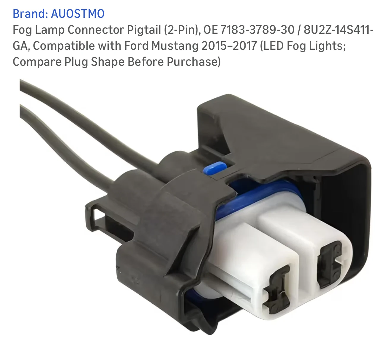
Connectors for the other end of my “sub” harness (I used Weather Pack connectors)
Various wiring components, heat shrink, wire ties, wire loom, etc.
I started by removing the driver’s side front fender inner liner. I believe there are 12 or 13 push style retainers with Phillips head all over, and 2 big head push tree retainers along the bottom front, and 4 screws/bolts holding it the fender itself. Remove all and maneuver the liner off and out. Also, before doing anything electrical with a car/truck, I always disconnect the negative battery terminal. It never hurts to be safe.

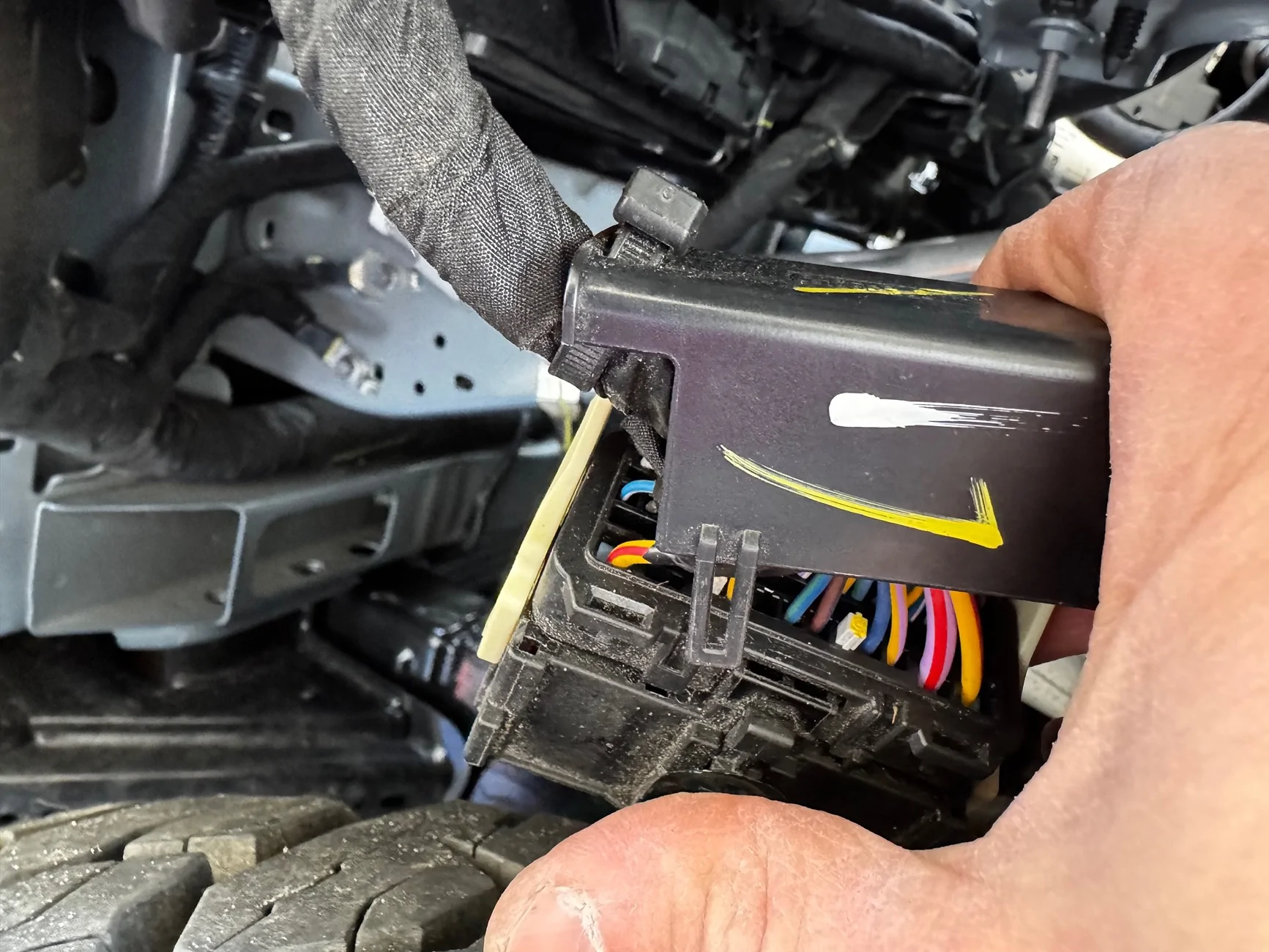
Connector C203 is on the top inside of the fender held there by a push tree-type clip. Get your fingers under it and pull the connector down so it’s easier to work with. There is a white lever holding the two sides together. Unlatch the lever, and the two sides will come apart.

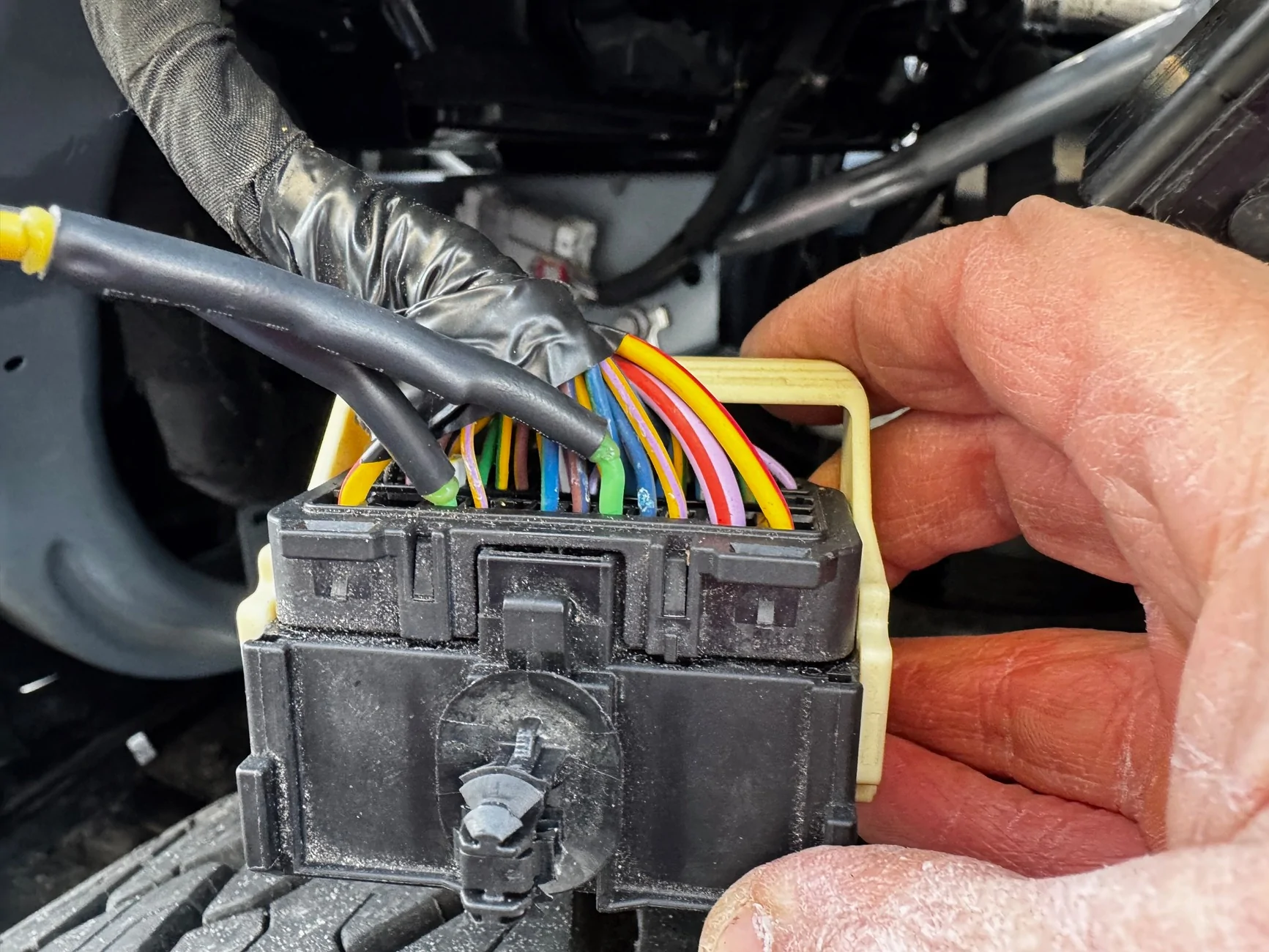
You will see on the male side of C203 (the side without the white lever) there are a brown wire and yellow/orange wire coming into pins 43 and 48.
If you remove the cover over the wires on the back of the female side of C203 (the side with the white lever) you will see there are grey plugs instead of the wires. I cut the wire tie holding the wire cover on the harness to put it to the side for the time being.
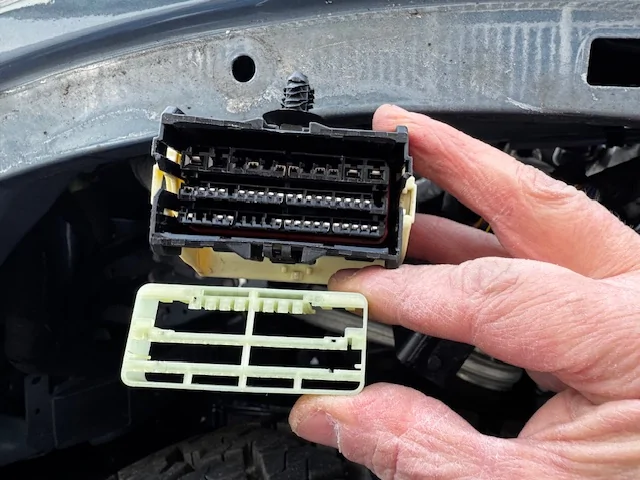
I used a crimp connector plus solder with heat shrink over it to connect the DU2Z-14474-DA repair terminal to my brown wire spool, and another one to connect to my yellow/orange wire spool. On the front of the female side of C203 (with the lever) the is a white retainer/lock to secure the terminals in the connector. Use a small flat head or tiny needle nose to pull this out.

On the back side, pull out the grey plugs on pins 43 and 48. Insert the correct terminal in the proper pin hole. Brown goes in pin 43, and Yellow/Orange goes in pin 48.
Push the white retainer back in the front of the connector to secure all the terminals. I gotta say that I was a little nervous that without the white retainer in, the rest of the terminals would fall out and I’d be left with a tangle mess. However, the other terminals were fairly secure in their slots so I worried about nothing. Next, I measured out the length of wire needed to route it to the tab for C192, cut, and put wire loom over my “sub” harness.
I secured the back wire cover of C203 on with a wire tie.
I plugged the connector C203 together making sure to latch the white lever, and pushed it back into place on the top of inside the fender. I routed my “sub” harness along the other wire harness using wire ties to the area of where connector C192 would be.
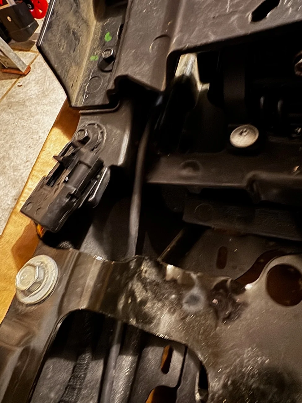
I am offering a disclaimer at this point; since I don’t have a connector C192 on my Bronco, I don’t really know if this is the tab that it goes to. It’s a tab in the same general location of where I believe C192 is, so I used it. Going through all the other posts about this wiring and these connectors, I could not find one clear picture of C192 nor the tab where is goes. So, if this is not the actual tab where it goes, please forgive the mistake. Anyway, I used a 3 pin Weather Pack connector as my C192 (one for brown, one for yellow/orange, and one for black/green or ground). I wired the Black/Green from my C192 to the nearest ground point I could see, reference the pic.
I then moved to the bumper. I wired the fog lights in the bumper to a 3 pin Weather Pack connector and secured it to the bottom inside of the bumper. I made up a short jumper harness to go between the bumper and my C192 on the body. I did this so it would be easy for me to disconnect the lights by either the bumper connection, or at my C192.
Installing the bumper was easy. 6 bolts for the bumper, 4 bolts for the skid plate, and 2 bolts each for the intercooler brackets. I then moved to the headlamp switch. I used switch number M2DZ-11654-CC, Motorcraft # SW-8846. I used this switch because I wanted the options of adding rear fog lights and spotlights at some point in the future.
To replace the headlamp switch, I got my fingers behind the panel that holds it, next to the steering column and just pulled. Give a quick tug and it pops down. I didn’t have to pull it all the way off; just enough to pop out the old switch.
Pull out the old switch, pull the plug off the back, plug in the new switch, pop new switch into panel, and push panel back on. Easy. Just don’t lose any of the light green clips that holds the panel on.
I reconnected the negative battery terminal. And then, it was on to the ForScan programming. I won’t go into great detail about the ForScan program or what is needed. I will just cut and paste what someone else has posted that worked for me too. But to save anyone the headache that I ran into, make sure to have the correct OBD driver on your Windows computer before trying to connect.
-----------------------------------------------------------
Connect to the vehicle and go into configurations --> BdyCM and open it.
You will want to find and change the following:
Front fog lamps - change this from "Disabled" to "Enabled".
Fog Lamp Switch - change this to "Enabled"
Using Front Fog With High Beam - This is an optional change but if you want to use fogs with high beams change it to "Allowed"
Write the settings made, you are finished with the BdyCM for now
Next you need to open the IPC which will turn on the fog light indicator in your gauge screen:
Front fog lamps - change this to "Enabled"
Write this setting and now we will go onto the As-Built change.
You will need to open BdyCM (As-Built Configuration). BACK UP THIS FILE in case anything goes wrong you can restore the original.
Locate the following line:
726-42-01-xxxx-xxxx-xxxx (My Big Bend specifically was 726-42-01-0000-0000-0575)
You will need to change the second box to 0101. ForScan does autochecksum calculations so what I ended up with was 726-42-01-0000-0101-0577”
--------------------------------------------------------------------
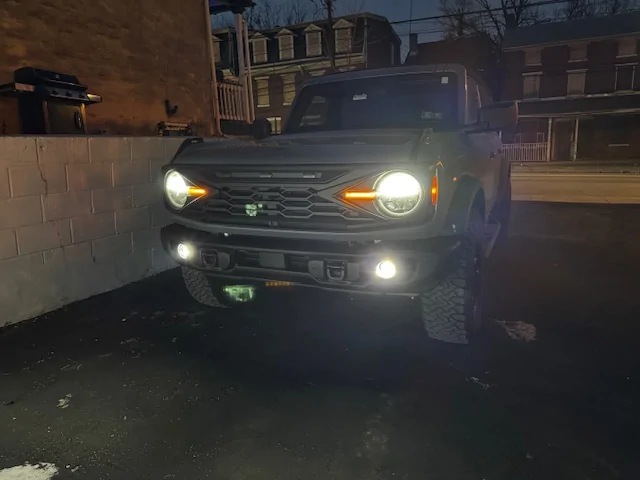
After I did the aforementioned ForScan programming changes, I was messing around in ForScan and am excited about all the changes I can and have made. It’s a really cool utility to have. After this, I turned on my Bronco and tested it out. Everything worked perfectly. The wiring was clean and tidy. Not ugly switches hanging off the dash. No wire taps or fuse taps.
This is what I did to have front fog lamps wired in my vehicle as close to the factory OEM as possible. At least at my ability. I’ve worked on cars and trucks all my life. I’ve rebuilt engines. I’ve built and restored many motorcycles. And, I worked in Fords parts for 5 years about 30 years ago. So, I have some mechanical and electrical experience. This post summarizes what I did. I am not saying any of this will work for you. But, I hope this information can be a reference for someone.
I have a ’25 Big Bend with no front parking sensors or front fogs. I was looking to swap out the standard plastic bumper with a steel capable bumper. The capable bumper I picked up on FB had the factory fog lights which put me on a quest to wire in the front fogs as close to factory as possible. If you’ve been down this road or researching it, you will know all Broncos have the front fog wires to connector C203. However, only Broncos with front parking sensors or front fog lights have the same wires exiting C203 to connector C192, which then connects to harness 15K867 and to the fogs lights in the bumper. My Big Bend Mid Package did not have any fog light wiring after C203. So, this is what I did:
The first step for me was to wire in a “sub” harness from connector C203 to a tab where connector C192 attaches in the front of driver’s side fender under the headlight. What I needed:
(2) Ford Terminal DU2Z-14474-DA
Brown 16GA wire (Left power feed)
Yellow/Orange 16GA wire (Right power feed)
Black/Green 16GA wire (Ground)
Connectors for the other end of my “sub” harness (I used Weather Pack connectors)
Various wiring components, heat shrink, wire ties, wire loom, etc.
I started by removing the driver’s side front fender inner liner. I believe there are 12 or 13 push style retainers with Phillips head all over, and 2 big head push tree retainers along the bottom front, and 4 screws/bolts holding it the fender itself. Remove all and maneuver the liner off and out. Also, before doing anything electrical with a car/truck, I always disconnect the negative battery terminal. It never hurts to be safe.

Connector C203 is on the top inside of the fender held there by a push tree-type clip. Get your fingers under it and pull the connector down so it’s easier to work with. There is a white lever holding the two sides together. Unlatch the lever, and the two sides will come apart.


You will see on the male side of C203 (the side without the white lever) there are a brown wire and yellow/orange wire coming into pins 43 and 48.

If you remove the cover over the wires on the back of the female side of C203 (the side with the white lever) you will see there are grey plugs instead of the wires. I cut the wire tie holding the wire cover on the harness to put it to the side for the time being.
I used a crimp connector plus solder with heat shrink over it to connect the DU2Z-14474-DA repair terminal to my brown wire spool, and another one to connect to my yellow/orange wire spool. On the front of the female side of C203 (with the lever) the is a white retainer/lock to secure the terminals in the connector. Use a small flat head or tiny needle nose to pull this out.
On the back side, pull out the grey plugs on pins 43 and 48. Insert the correct terminal in the proper pin hole. Brown goes in pin 43, and Yellow/Orange goes in pin 48.
Push the white retainer back in the front of the connector to secure all the terminals. I gotta say that I was a little nervous that without the white retainer in, the rest of the terminals would fall out and I’d be left with a tangle mess. However, the other terminals were fairly secure in their slots so I worried about nothing. Next, I measured out the length of wire needed to route it to the tab for C192, cut, and put wire loom over my “sub” harness.
I secured the back wire cover of C203 on with a wire tie.

I plugged the connector C203 together making sure to latch the white lever, and pushed it back into place on the top of inside the fender. I routed my “sub” harness along the other wire harness using wire ties to the area of where connector C192 would be.

I am offering a disclaimer at this point; since I don’t have a connector C192 on my Bronco, I don’t really know if this is the tab that it goes to. It’s a tab in the same general location of where I believe C192 is, so I used it. Going through all the other posts about this wiring and these connectors, I could not find one clear picture of C192 nor the tab where is goes. So, if this is not the actual tab where it goes, please forgive the mistake. Anyway, I used a 3 pin Weather Pack connector as my C192 (one for brown, one for yellow/orange, and one for black/green or ground). I wired the Black/Green from my C192 to the nearest ground point I could see, reference the pic.

I then moved to the bumper. I wired the fog lights in the bumper to a 3 pin Weather Pack connector and secured it to the bottom inside of the bumper. I made up a short jumper harness to go between the bumper and my C192 on the body. I did this so it would be easy for me to disconnect the lights by either the bumper connection, or at my C192.
Installing the bumper was easy. 6 bolts for the bumper, 4 bolts for the skid plate, and 2 bolts each for the intercooler brackets. I then moved to the headlamp switch. I used switch number M2DZ-11654-CC, Motorcraft # SW-8846. I used this switch because I wanted the options of adding rear fog lights and spotlights at some point in the future.
To replace the headlamp switch, I got my fingers behind the panel that holds it, next to the steering column and just pulled. Give a quick tug and it pops down. I didn’t have to pull it all the way off; just enough to pop out the old switch.

Pull out the old switch, pull the plug off the back, plug in the new switch, pop new switch into panel, and push panel back on. Easy. Just don’t lose any of the light green clips that holds the panel on.

I reconnected the negative battery terminal. And then, it was on to the ForScan programming. I won’t go into great detail about the ForScan program or what is needed. I will just cut and paste what someone else has posted that worked for me too. But to save anyone the headache that I ran into, make sure to have the correct OBD driver on your Windows computer before trying to connect.
-----------------------------------------------------------
Connect to the vehicle and go into configurations --> BdyCM and open it.
You will want to find and change the following:
Front fog lamps - change this from "Disabled" to "Enabled".
Fog Lamp Switch - change this to "Enabled"
Using Front Fog With High Beam - This is an optional change but if you want to use fogs with high beams change it to "Allowed"
Write the settings made, you are finished with the BdyCM for now
Next you need to open the IPC which will turn on the fog light indicator in your gauge screen:
Front fog lamps - change this to "Enabled"
Write this setting and now we will go onto the As-Built change.
You will need to open BdyCM (As-Built Configuration). BACK UP THIS FILE in case anything goes wrong you can restore the original.
Locate the following line:
726-42-01-xxxx-xxxx-xxxx (My Big Bend specifically was 726-42-01-0000-0000-0575)
You will need to change the second box to 0101. ForScan does autochecksum calculations so what I ended up with was 726-42-01-0000-0101-0577”
--------------------------------------------------------------------
After I did the aforementioned ForScan programming changes, I was messing around in ForScan and am excited about all the changes I can and have made. It’s a really cool utility to have. After this, I turned on my Bronco and tested it out. Everything worked perfectly. The wiring was clean and tidy. Not ugly switches hanging off the dash. No wire taps or fuse taps.
This is what I did to have front fog lamps wired in my vehicle as close to the factory OEM as possible. At least at my ability. I’ve worked on cars and trucks all my life. I’ve rebuilt engines. I’ve built and restored many motorcycles. And, I worked in Fords parts for 5 years about 30 years ago. So, I have some mechanical and electrical experience. This post summarizes what I did. I am not saying any of this will work for you. But, I hope this information can be a reference for someone.
Sponsored
Last edited: