- Joined
- Jun 3, 2019
- Threads
- 24
- Messages
- 999
- Reaction score
- 3,288
- Location
- Plymouth Michigan
- Vehicle(s)
- 2021 Bronco Badlands non-sas 4 door manual
- Your Bronco Model
- Badlands
- Thread starter
- #1
Hey guys, here's a video I put together about the design and fabrication of a diff drop for my own Bronco. I suck at making short youtube videos, I always end up rambling on in detail but I think some of you on the forum are in to that. (Now available here: Differential Drop Kits — Products — Broken Innovation)
I'll share pictures and write up as well for those who prefer to read. (all this is covered in the video)
For those who don’t know, the primary goal of a diff drop is to reduce the CV angle at max rebound (max droop). Any spacer lift, or extended travel coil over will lower the rebound position of the wheel with respect to the differential and thus increase the CV angle. Strength of a CV joint is proportional to the operating angle, so even if a lift kit keeps the CV angle within an operational range with no binding, it still could have serious consequences for the strength. I went with ICON coil overs primarily to maximize my wheel travel which is why I made this diff drop.
Before you go and just drop your differential, a couple things need to be considered.
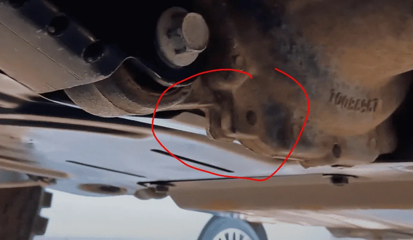
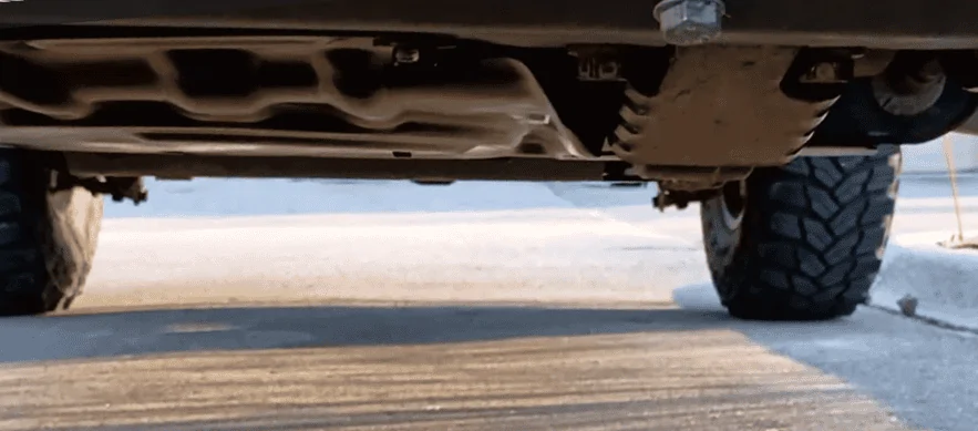
1: Ground clearance. A well-designed IFS system should have the differential be the limiting factor for ground clearance (no unnecessarily low brackets and components). See here how the differential protruded through the skidplate. Obviously dropping the diff will affect clearance here.

2: (more important) Plunge. Visualize the front suspension as a 2D model of a 4 bar linkage (frame, knuckle, and upper/lower control arms). The positioning of the inner and outer CV is critical for the axle to move freely and parallel to the suspension. Moving the differential downward misaligns the motion of the CV through suspension travel which means it will now plunge in and out more than intended. There is an allowable amount of plunge for a CV which again is tied to the angle. When the CV is straight it can plunge the most, in this case about 20mm in and out. When the CV is maxed out at 30°, the plunge is reduced to only about 10mm in and out.
I chose 20mm drop for my differential drop because that just about maximized the CV plunge I have available. If I were to drop further, 25mm or 30, even though the CV is at a lower angle, the plunge has exceeded the design limits and something in the system will be stressed excessively.
Here you can see the max CV angles in jounce and rebound for both the stock and icon equipped suspension. And for the standard differential position vs the 20mm drop position. Just putting on Icon suspension increased my max CV angle at full rebound by 50%! The 20mm diff drop reduces the max angle by over 3° or almost 12% reduced. Still not as good as stock, but a significant improvement vs where the ICONs were.

Ok, so now that I've established why I wanted a 20mm drop, I'll breakdown how I decided to achieve that.
The two main considerations I had when designing this diff drop were 1: strength/durability, and 2: ease of fabrication, specifically ease of fabricating it correctly. (dont want to do all this math and miss the mark.). With both of these in mind I came up with a relatively simple 2 piece design for the main bracket, where each peice could be relatively easily bend into the desired form. Bending 1/4" plate was more of a challenge than I anticipated. I first bought a cheap $50 vice break and shattered that. So, I coughed up the cash for a much beefier (and pricier) break, under the justification that I will use it for decades to come. This could have been avoided by fabricating more smaller pieces and welding them into form, but that was at least a partial compromise to my 2 most important considerations listed above.
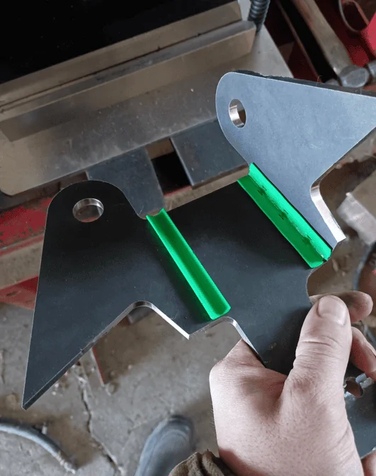
Even with my relatively simple design, getting precise bends was a challenge. My first attempt was too far off the mark, on my second attempt I made little plastic guides to help align the break exactly before bending (3D printed green).


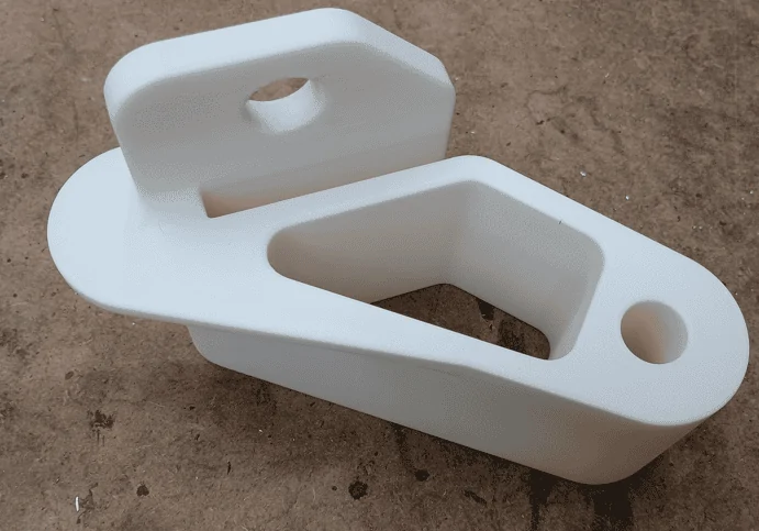
Welding up the parts was rather easy. First, I used a 3D printed gauge to check that the bent parts held position of the holes correctly as well as the width of the flanges. I also used this gauge to hold everything in place for spot welding the parts together.


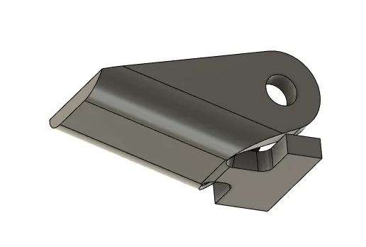
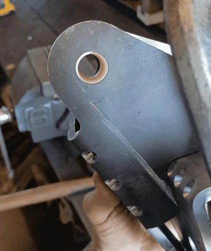
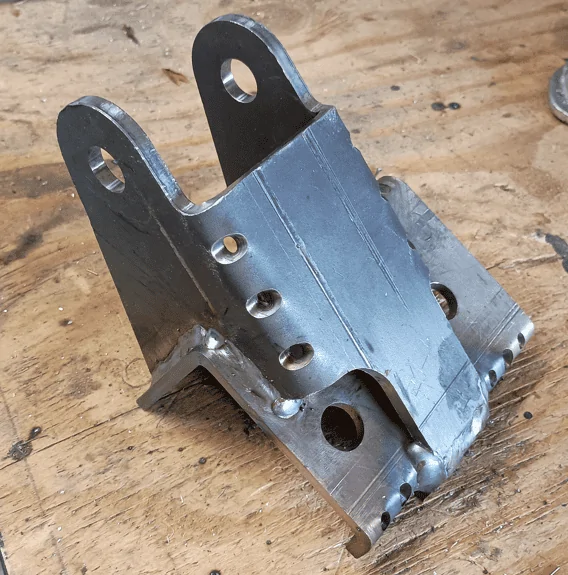
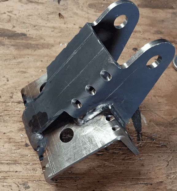
Here's the bracket welded up prior to painting:


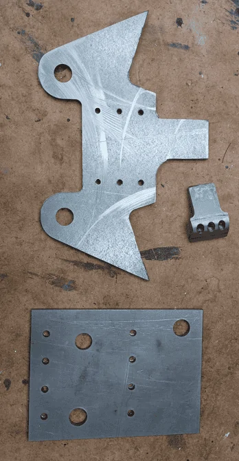
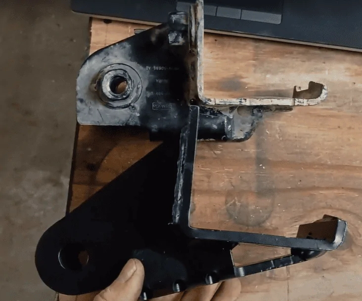
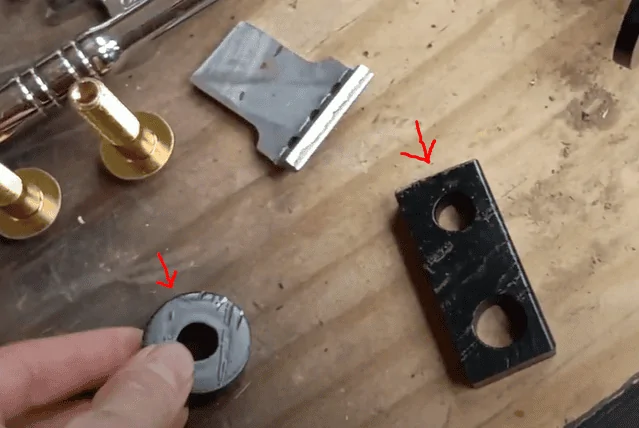
Here it is side by side with the OEM bracket, as well as the two less interesting but equally important parts of the kit:


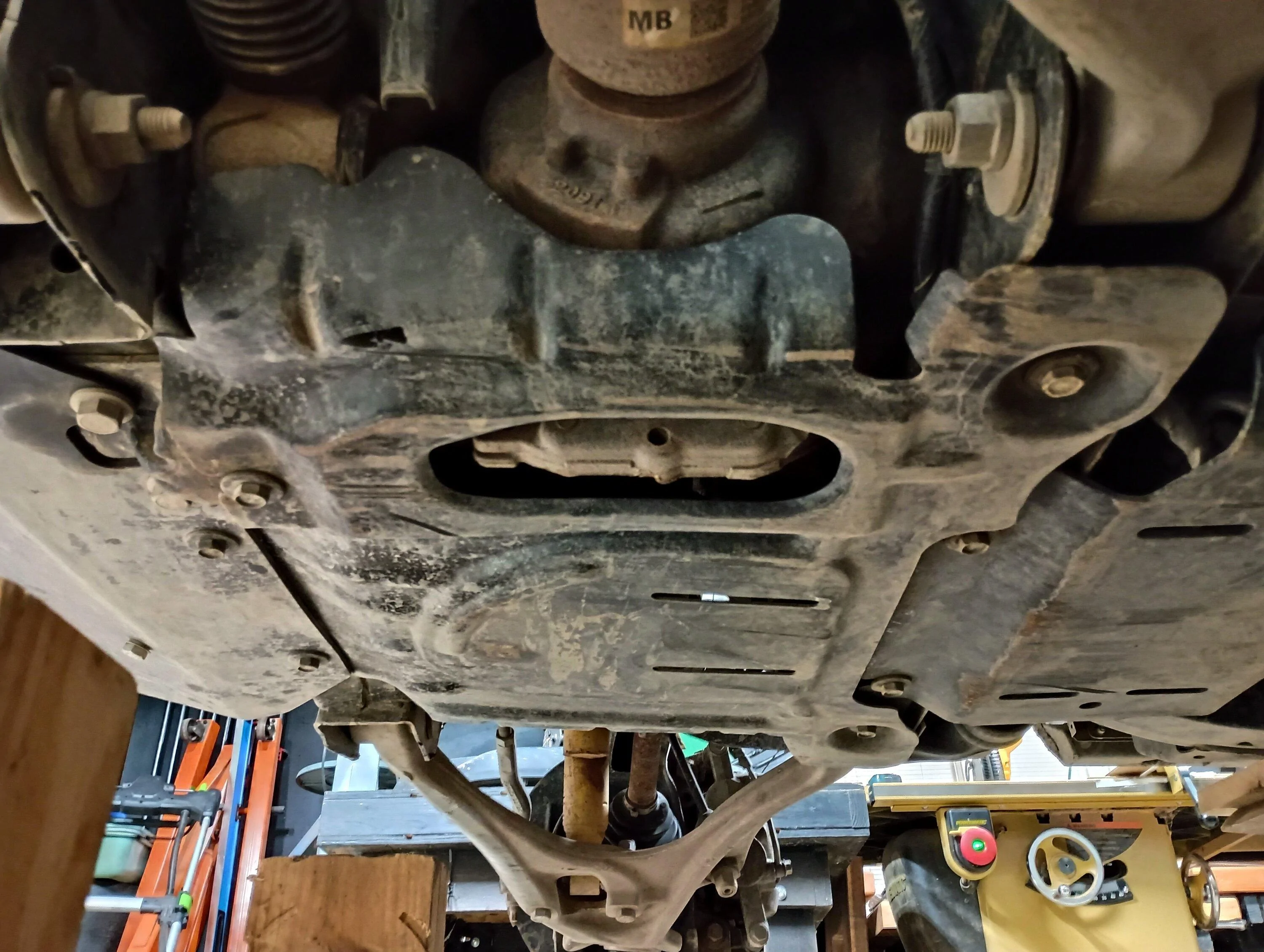
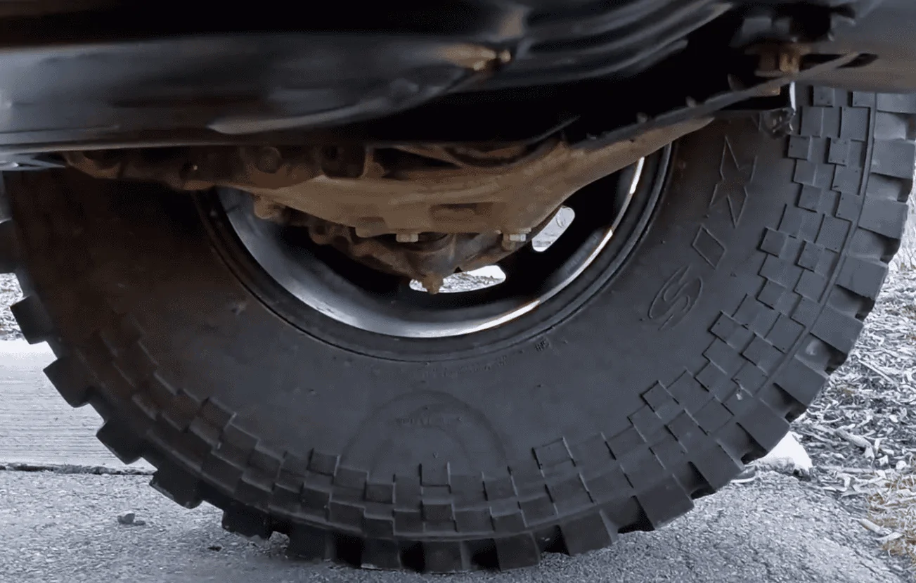
Fully Installed:


----------------------------------------------------------------
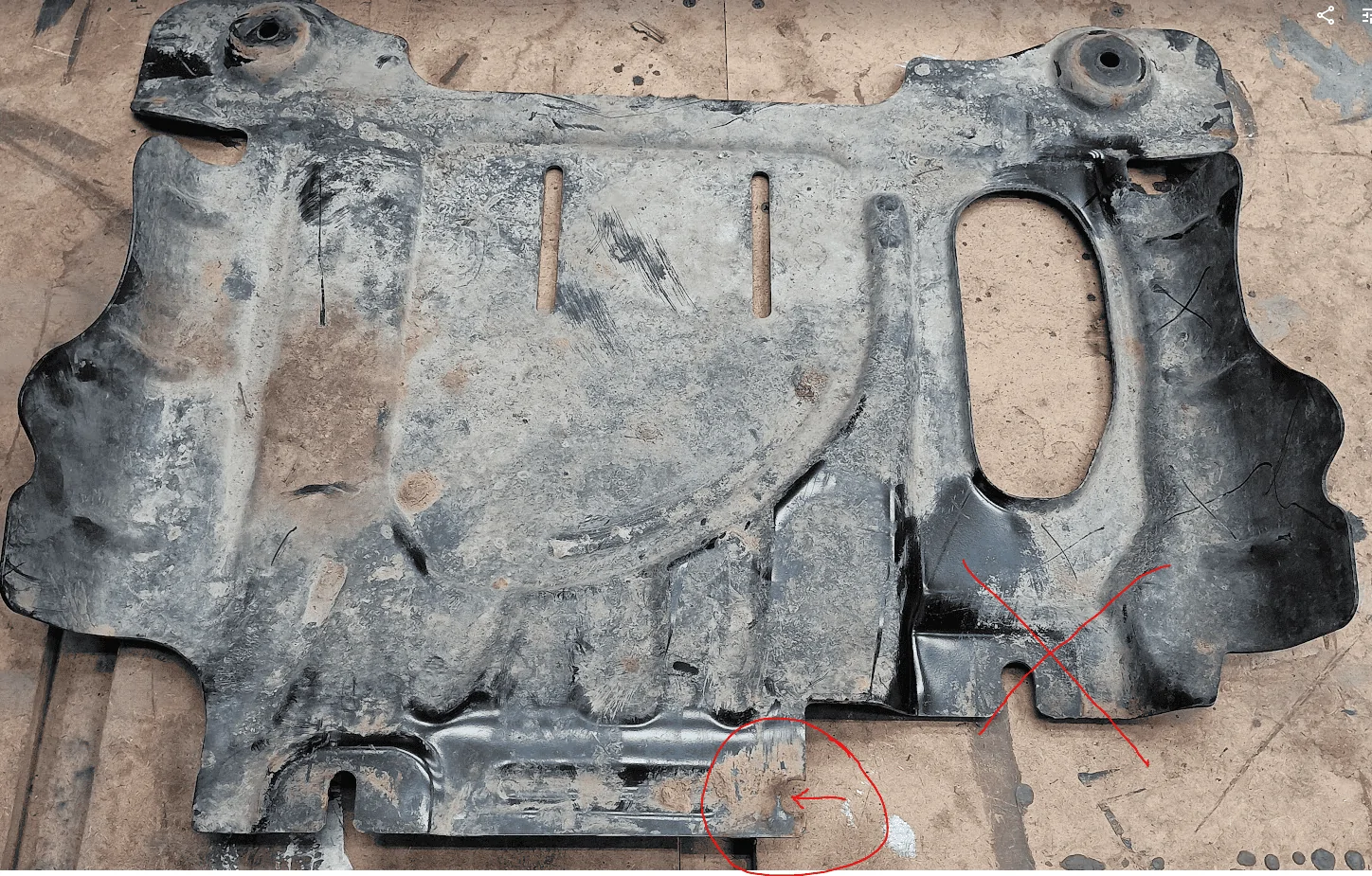
Update: Regarding customization of the skidplate. The OEM badlands skid plate has only 4 bolts holding it in, In these photos, you may notice that there are 5, and later the bolt which used the OEM diff bracket was removed.
This middle bolt is using an otherwise unused weldnut available right next to the diff bracket. I had previously modified my skidplate to use that additional weldnut per the install instructions for the Lobo hidden winch skidplate. I later forgot that that was a modification I made and thus forgot to mention it here.
If you modify your OEM skid plate with this diff drop, and lose the mounting attachment there, you will definitely want to modify your skid to accept a bolt in the unused hole next to the diff bracket.
From Lobo:

My modified skid with new hole:

I'll share pictures and write up as well for those who prefer to read. (all this is covered in the video)
For those who don’t know, the primary goal of a diff drop is to reduce the CV angle at max rebound (max droop). Any spacer lift, or extended travel coil over will lower the rebound position of the wheel with respect to the differential and thus increase the CV angle. Strength of a CV joint is proportional to the operating angle, so even if a lift kit keeps the CV angle within an operational range with no binding, it still could have serious consequences for the strength. I went with ICON coil overs primarily to maximize my wheel travel which is why I made this diff drop.
Before you go and just drop your differential, a couple things need to be considered.
1: Ground clearance. A well-designed IFS system should have the differential be the limiting factor for ground clearance (no unnecessarily low brackets and components). See here how the differential protruded through the skidplate. Obviously dropping the diff will affect clearance here.
2: (more important) Plunge. Visualize the front suspension as a 2D model of a 4 bar linkage (frame, knuckle, and upper/lower control arms). The positioning of the inner and outer CV is critical for the axle to move freely and parallel to the suspension. Moving the differential downward misaligns the motion of the CV through suspension travel which means it will now plunge in and out more than intended. There is an allowable amount of plunge for a CV which again is tied to the angle. When the CV is straight it can plunge the most, in this case about 20mm in and out. When the CV is maxed out at 30°, the plunge is reduced to only about 10mm in and out.
I chose 20mm drop for my differential drop because that just about maximized the CV plunge I have available. If I were to drop further, 25mm or 30, even though the CV is at a lower angle, the plunge has exceeded the design limits and something in the system will be stressed excessively.
Here you can see the max CV angles in jounce and rebound for both the stock and icon equipped suspension. And for the standard differential position vs the 20mm drop position. Just putting on Icon suspension increased my max CV angle at full rebound by 50%! The 20mm diff drop reduces the max angle by over 3° or almost 12% reduced. Still not as good as stock, but a significant improvement vs where the ICONs were.

Ok, so now that I've established why I wanted a 20mm drop, I'll breakdown how I decided to achieve that.
The two main considerations I had when designing this diff drop were 1: strength/durability, and 2: ease of fabrication, specifically ease of fabricating it correctly. (dont want to do all this math and miss the mark.). With both of these in mind I came up with a relatively simple 2 piece design for the main bracket, where each peice could be relatively easily bend into the desired form. Bending 1/4" plate was more of a challenge than I anticipated. I first bought a cheap $50 vice break and shattered that. So, I coughed up the cash for a much beefier (and pricier) break, under the justification that I will use it for decades to come. This could have been avoided by fabricating more smaller pieces and welding them into form, but that was at least a partial compromise to my 2 most important considerations listed above.
Even with my relatively simple design, getting precise bends was a challenge. My first attempt was too far off the mark, on my second attempt I made little plastic guides to help align the break exactly before bending (3D printed green).

Welding up the parts was rather easy. First, I used a 3D printed gauge to check that the bent parts held position of the holes correctly as well as the width of the flanges. I also used this gauge to hold everything in place for spot welding the parts together.
Here's the bracket welded up prior to painting:

Here it is side by side with the OEM bracket, as well as the two less interesting but equally important parts of the kit:
Fully Installed:

----------------------------------------------------------------
Update: Regarding customization of the skidplate. The OEM badlands skid plate has only 4 bolts holding it in, In these photos, you may notice that there are 5, and later the bolt which used the OEM diff bracket was removed.
This middle bolt is using an otherwise unused weldnut available right next to the diff bracket. I had previously modified my skidplate to use that additional weldnut per the install instructions for the Lobo hidden winch skidplate. I later forgot that that was a modification I made and thus forgot to mention it here.
If you modify your OEM skid plate with this diff drop, and lose the mounting attachment there, you will definitely want to modify your skid to accept a bolt in the unused hole next to the diff bracket.
From Lobo:
My modified skid with new hole:
Sponsored
Last edited: