Sponsored

Ducati1098

Wildtrak
Well-Known Member
Joined
Jul 14, 2020
Threads
11
Messages
3,723
Reaction score
7,427
Location
Midwest
Vehicle(s)
2022 Bronco Wildtrak, 2012 Ford Fusion
Your Bronco Model
Wildtrak
Clubs
 
Brand new version downloaded from the site today. Whatever updates it suggested during install I had it do. I did get an email that FDRS server was down on the 15th...woulda thought it's fixed by now, but who knows what the rockstars effed up this time. For vehicle connection I use a j2534 device. It works, I am flashing the PCM on an 04 Ranger as I type this. FDRS detected my device just fine, and detected the Bronco's VIN just fine, it just doesn't know wtf a 22 Bronco is. Makes sense if it can't access the online library to decode the VIN tho...gives me hope!
Interesting. Yeah I’m assuming it’s just some issue with Ford then. I’ll try and connect to my 22 Wildtrak tomorrow at work and see what happens.
Sponsored


Bmadda

Badlands
Well-Known Member
First Name
Brian
Joined
Jul 18, 2020
Threads
20
Messages
2,717
Reaction score
6,224
Location
Wisconsin USA
Vehicle(s)
1990 Bronco eddie bauer
Your Bronco Model
Badlands
So I got into the tool finally and if I click on PMI for PSCM I get this message:

20220818_083102.jpg
 

flip

Badlands
Well-Known Member
Base Sponsor (Level 1)
First Name
Phil
Joined
Jul 21, 2020
Threads
41
Messages
4,310
Reaction score
14,278
Location
IN
Website
www.ruxerparts.com
Vehicle(s)
Fords
Your Bronco Model
Badlands
Clubs
 
Steering Gear
Removal

NOTE:
Removal steps in this procedure may contain installation details.

  1. If installing a new steering gear, connect the scan tool and upload the module configuration information from the PSCM .
    Refer to: Module Programming (418-01A Module Configuration, General Procedures).
  1. NOTE: Do not allow the steering column to rotate while the steering column shaft is disconnected or damage to the steering column internal sensor may result.
    Using a holding device, hold the steering wheel in the straight-ahead position.
Ford Bronco {thread} {filename}
  1. Remove the front axle assembly.
    Refer to: Axle Assembly (205-03A Front Drive Axle/Differential, Removal and Installation).
  1. Ford Bronco {thread} {filename}
    WARNING: Do not reuse steering column shaft bolts. This may result in fastener failure and steering column shaft detachment or loss of steering control. Failure to follow this instruction may result in serious injury to vehicle occupant(s).
    NOTICE: Do not allow the steering wheel to rotate while the steering column shaft is disconnected or damage to the clockspring may result.
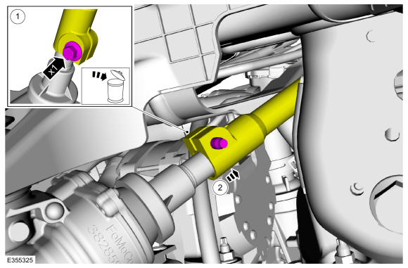
    1. Remove and discard the steering column shaft coupler retainer.
      Torque: 22 lb.ft (30 Nm)
    1. Separate the lower steering column shaft from the steering gear.
Ford Bronco {thread} {filename}
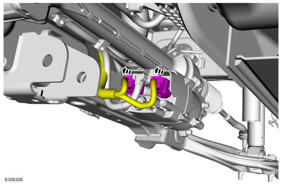
  1. Disconnect the EPAS gear electrical connectors.
Ford Bronco {thread} {filename}

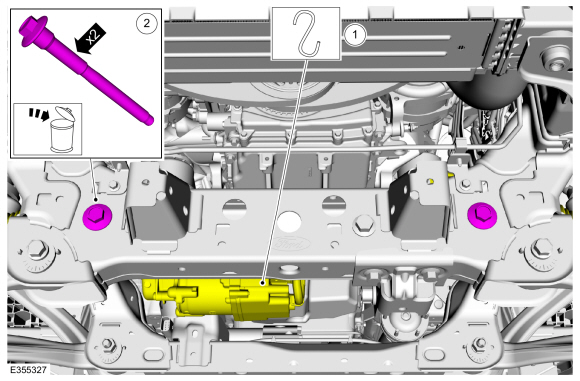
  1. Remove the EPAS gear retainers.
    1. Support the EPAS gear assembly.
    1. Remove and discard the EPAS gear retainers.
      Torque: 184 lb.ft (250 Nm)
Ford Bronco {thread} {filename}

  1. Remove the EPAS gear.
    1. Rotate the EPAS gear tower downward.
    1. Shift the EPAS gear toward the RH side of the vehicle.
    1. Remove the EPAS gear.
Ford Bronco {thread} {filename}
Installation

  1. To install, reverse the removal procedure.
  1. If a new steering gear was installed, download the PSCM configuration from the scan tool to the new PSCM .
    Refer to: Module Programming (418-01A Module Configuration, General Procedures).
  1. Check and if necessary, adjust front toe.
    Refer to: Front Toe Adjustment (204-00 Suspension System - General Information, General Procedures).
 

flip

Badlands
Well-Known Member
Base Sponsor (Level 1)
First Name
Phil
Joined
Jul 21, 2020
Threads
41
Messages
4,310
Reaction score
14,278
Location
IN
Website
www.ruxerparts.com
Vehicle(s)
Fords
Your Bronco Model
Badlands
Clubs
 
Module Programming
Check

NOTE:
Perform the following pre-checks to make sure module programming completes without errors.

  1. Start the programming session in Key OFF, Engine OFF and prior to initiating programming, turn to KOEO .
  1. Make sure the vehicle battery is fully charged or is connected to a battery charger. The battery state of charge should be 12.6 - 13.6 volts during vehicle programming.
  1. NOTE: A good internet connection is necessary.
    Inspect the VCM II, VCMM or later level device and cables for damage. Make sure cables remain connected throughout the programming procedure.
  1. Turn off all unnecessary accessories, such as radio, A/C , climate controlled seats, headlamps, interior and demand lamps.
  1. Disconnect any aftermarket accessories, such as remote start, security alarm and power inverter.
  1. For Plug-in hybrid and electric vehicles, disconnect the external charge cord from the charge port.
  1. Disable Microsoft Windows sleep mode, screensaver and hibernation modes.
  1. NOTE: If the diagnostic software does not load or if the vehicle cannot be identified properly.
    Make sure there is a good internet connection and the VCM II, VCMM or later level device is properly connected to the DLC .
Programming

  1. NOTE: If a new module is being installed, install the new module before carrying out the following procedure.
      • If replacing the module do not connect the new module to a Wi-Fi network before completing the scan tool module replacement programming as it may cause programming concerns.
      • This programming procedure deletes any phones that are paired with the SYNC system when programming the APIM .
      • To prevent time-out errors and minimize programming time, a wired internet connection is strongly recommended when programming.
      • Make sure the FDRS version and patch software levels are up to date.

  2. Connect a battery charger to the vehicle and select the low charge setting. The negative battery charger lead must be connected to a clean chassis ground, not the negative battery post.
  1. Connect the diagnostic scan tool to a power supply. The length of time required for programming may extend past the duration of the diagnostic scan tool.
  1. Connect the diagnostic scan tool to the DLC .
  1. Log into FDRS .
  1. Identify/enter the vehicle being programmed on FDRS .
  1. NOTE: Vehicle information is automatically retrieved by the diagnostic software and a Network Test is run. Vehicle identification data appears on the screen when this is complete.
    Click 'Read VIN from Vehicle' or manually enter the VIN .
  1. NOTE: Available modules are shown on the LH side of the screen, and available procedures are listed on the RH side of the screen. Modules that are communicating are highlighted in green.
    Select Toolbox tab.
  1. NOTE: If a module is integrated within another module, both modules will automatically program during this process. For example, if the ACM is selected, the DACMC (if integrated with the ACM ) is also programmed.
    From the list on the LH side of the screen, select the module that requires a programming procedure to be completed.
  1. There are 3 types of module programming available:
    • Programmable Module Installation (PMI)—When the module is replaced, this type of programming carries out the required provisioning (restores software for newly installed hardware).
    • Module configuration — Downloads configuration data to the module. The module may also be programmed, depending on current software level, when this option is selected.
    • Software Update— Updates the module and any currently installed applications to the latest software levels. This option is not available if the module is already at the latest level.
  1. From the list on the RH side of the screen, select PMI Software Update or Module Configuration.
  1. NOTE: Do not disconnect the VCM from the DLC during the module programming process unless directed by the diagnostic scan tool on-screen prompts.
    Follow all on-screen instructions carefully.
  1. After programming is complete, "Programming has been successfully completed" displays.
Programming

NOTE:
If updating using a USB memory device.

  1. Connect a battery charger to the vehicle 12V battery. Set the charger to maintain 12.6 - 13.6 volts.
  1. Connect the VCM II, VCMM or later level device to the vehicle DLC and the diagnostic scan tool USB port.
  1. Log into FDRS .
  1. NOTE: Vehicle information is automatically retrieved by the diagnostic software and a Network Test is run. Vehicle identification data appears on the screen when this is complete.
    Click 'Read VIN from Vehicle' or manually enter the VIN .
  1. NOTE: Available modules are shown on the LH side of the screen, and available procedures are listed on the RH side of the screen. Modules that are communicating are highlighted in green.
    Select Toolbox tab.
  1. NOTE: If the module is already at the latest software level, the software update application will not be available in the diagnostic scan tool.
    If replacing the module, download and run the PMI . If the module is not being replaced but is receiving a software update in accordance with a TSB or service publication, download and run the software update application for the target module.
  1. Close all doors or mechanically latch the door to simulate a closed door.
  1. Follow the on-screen prompts to complete the PMI .
  1. On-screen prompts are displayed to inform that a USB is required to complete the process.
  1. Follow the on-screen instructions to download the required software to the USB memory device and upload to the vehicle though the vehicle USB port.
  1. Once the USB memory device is connected to the media hub or USB port, the software update will automatically install. The USB memory device transfers the data through the USB cable to the APIM . The APIM transfers the data to the GWM where it is distributed to the receiving module over the Ethernet network.
  1. It is advised that the USB memory device remain connected to the vehicle for a minimum of 2 minutes after the progress bar displayed on the vehicle display screen has reached 100%, to ensure the upload has completed fully.
  1. If an error occurs during the USB programming process an error message is displayed on the vehicle display screen indicating an error has occurred and displays an error number relating to the type of error that occurred. REFER to the Error Condition Table below for a description and action to be taken, if an error message is displayed.


    Error Condition Table
    Vehicle display screen Error MessageCauseAction
    USB Error 1CacheFullDelete all contents on the USB memory device/ Format the USB memory device. Re-run the PMI routine with the diagnostic scan tool and re attempt the PMI . If the PMI fails again, attempt a CAN flash, following the diagnostic scan tool on-screen instructions.
    USB Error 2ManifestinvalidDelete all contents on the USB memory device/ Format the USB memory device. Re-run the PMI routine with the diagnostic scan tool and re attempt the PMI . If the PMI fails again, attempt a CAN flash, following the diagnostic scan tool on-screen instructions.
    USB Error 3InstallationPackageErrorDelete all contents on the USB memory device/ Format the USB memory device. Re-run the PMI routine with the diagnostic scan tool and re attempt the PMI . If the PMI fails again, attempt a CAN flash, following the diagnostic scan tool on-screen instructions.
    USB Error 4USBRemoved
    • Make sure the USB memory device is installed in the vehicle until the vehicle display screen indicates programming was successful and the USB memory device can be removed.
    • Using a diagnostic scan tool carry out the APIM self -test and verify there are no USB cable or media hub related Diagnostic Trouble Codes (DTCs).
    • Verify USB / media hub functionality by using the MIT , a mobile phone connected via a USB charge cord and/or a USB memory device with media files loaded.
    • Remove and reinsert the USB memory device and retry programming.
    • Attempt programming with a different USB memory device.
    USB Error 5InstallSignatureDelete all contents on the USB memory device/ Format the USB memory device. Re-run the PMI routine with the diagnostic scan tool and re attempt the PMI . If the PMI fails again, attempt a CAN flash, following the diagnostic scan tool on-screen instructions.
    USB Error 6RebootReset
    • Do not perform a master reset or SYNC hard reset during the USB programming. Make sure active resets are finished and the SYNC system has rebooted before re-attempting the USB programming.
    • Test the vehicle's 12 volt vehicle battery using approved diagnostic battery testers. Fully recharge or replace the battery per the test results. Complete the Battery Monitoring System (BMS) reset after the battery service, if directed by the workshop manual procedure. Retry the programming.
    USB Error 7USBReadError
    • Make sure the USB memory device is installed in the vehicle until the vehicle display screen indicates programming was successful and the USB can be removed.
    • Using a diagnostic scan tool carry out the APIM self -test and verify there are no USB cable or media hub related Diagnostic Trouble Codes (DTCs).
    • Verify USB / media hub functionality by using the MIT , a mobile phone connected via a USB charge cord and/or a USB memory device with media files loaded.
    • Remove and reinsert the USB memory device and retry programming.
    • Attempt programming with a different USB memory device.
    USB Error 8USBWriteError
    • Make sure the USB memory device used for the update is a 32GB, Exfat formatted USB memory device.
    • Attempt programming with the correctly formatted USB memory device or a different 32GB, Exfat formatted USB memory device.
    USB Error 9BatVoltageLowTest the vehicle 12 volt battery using approved diagnostic battery testers. Fully recharge or replace the battery per the test results. Complete the Battery Monitoring System (BMS) reset after the battery service, if directed by the workshop manual procedure. Retry the programming.
    USB Error 10USBWrongFilesMake sure the correct files have been downloaded to the USB memory device.
    USB Error 11VehicleModesMake sure the vehicle's ignition is in the key on, engine off state. Verify the vehicle is in park/neutral.
    USB Error 12eCallPhoneVerify that any paired mobile phones are not making a Bluetooth connected call through the SYNC system.
    USB Error 13CrashUsing a diagnostic scan tool carry out the OCSM and RCM self-test. Verify there are no crash related Diagnostic trouble codes (DTCs) stored. Diagnose any related codes and reattempt to reprogram the vehicle.
    USB Error 14IgnitionCycle
    • Make sure the vehicle ignition remains in the key on, engine off state during programming. The LED indicator on the ignition push button remains flashing when in key on, engine off state. Low battery state of charge or battery health may cause battery load shed strategies to shut the ignition off during programming.
    • Test the 12-volt battery using an approved diagnostic battery tester. Fully recharge or replace the battery per the tester results. Once complete, carry out the Battery Monitor System (BMS) reset with the scan tool.
    • Reattempt the programming.
    USB Error 15MasterResetDo not perform a master reset or SYNC hard reset during the USB programming. Make sure active resets are finished and the SYNC system has rebooted before re-attempting the USB programming.
Recovery

NOTE:
Perform the following steps when programming has resulted in a blank module.

  1. Disconnect the VCM II, VCMM or later level device from the DLC and PC.
  1. Launch FDRS and log in.
  1. In the Device Manager window that populates, select CANCEL.
  1. Select the appropriate VIN from the Vehicle Identification menu or use Manual VIN Entry and select GO.
  1. In the Vehicle Communication Device Not Detected window that populates, select CONTINUE. If a Device Explorer window populates, select CANCEL.
  1. After the session has started, reconnect the VCM II/ VCMM to the DLC and the PC. The VCM II/ VCMM or later level device icon should turn green in the bottom right corner of the screen. If it does not, troubleshoot the FDRS to VCM II, VCMM or later level device connection.
  1. In the Toolbox menu, navigate to the failed module and Download/Run PMI . Follow the on-screen prompts. When asked if the original module is installed, select NO and continue through the installation application.
  1. Once programming has completed, a screen may list additional steps required to complete the programming process. Make sure all applicable steps are followed in order.
 

Sponsored

Ducati1098

Wildtrak
Well-Known Member
Joined
Jul 14, 2020
Threads
11
Messages
3,723
Reaction score
7,427
Location
Midwest
Vehicle(s)
2022 Bronco Wildtrak, 2012 Ford Fusion
Your Bronco Model
Wildtrak
Clubs
 
So I got into the tool finally and if I click on PMI for PSCM I get this message:

Ford Bronco HOSS 3.0 severe duty STEERING RACK and TIE RODS ...Ford Performance M-3200-WT Hel
That picture shows that you have no communication between your device and FDRS.
 

Bmadda

Badlands
Well-Known Member
First Name
Brian
Joined
Jul 18, 2020
Threads
20
Messages
2,717
Reaction score
6,224
Location
Wisconsin USA
Vehicle(s)
1990 Bronco eddie bauer
Your Bronco Model
Badlands
That picture shows that you have no communication between your device and FDRS.
Nevermind...that was my fault. I still had FJDS open from last night on that Ranger I was trying to finish. It was still in PATS security access mode because (OF COURSE) the customer only has one key. No matter how patiently I explain that EVERY Ford product built since PATS was added has 2 keys programmed, they claim the vehicle only ever had one...even though we know that is physically impossible. Didn't know FDRS and FJDS talk to each other, but apparently they do.
 

Bmadda

Badlands
Well-Known Member
First Name
Brian
Joined
Jul 18, 2020
Threads
20
Messages
2,717
Reaction score
6,224
Location
Wisconsin USA
Vehicle(s)
1990 Bronco eddie bauer
Your Bronco Model
Badlands
That picture shows that you have no communication between your device and FDRS.
I was doing it outside and couldn't get a pic because of the sun glare. I just brought the computer inside to snap a pic. The little button at the bottom was green when it was plugged in. Is that what you are referring to?
 

Sponsored

Ducati1098

Wildtrak
Well-Known Member
Joined
Jul 14, 2020
Threads
11
Messages
3,723
Reaction score
7,427
Location
Midwest
Vehicle(s)
2022 Bronco Wildtrak, 2012 Ford Fusion
Your Bronco Model
Wildtrak
Clubs
 
I was doing it outside and couldn't get a pic because of the sun glare. I just brought the computer inside to snap a pic. The little button at the bottom was green when it was plugged in. Is that what you are referring to?
Yeah, I just assumed it was still connected. Disregard my comment. It might still be an issue with Ford. Hard to tell. At least you are able to read the vehicle now lol
 

Bmadda

Badlands
Well-Known Member
First Name
Brian
Joined
Jul 18, 2020
Threads
20
Messages
2,717
Reaction score
6,224
Location
Wisconsin USA
Vehicle(s)
1990 Bronco eddie bauer
Your Bronco Model
Badlands
Ok, so this sucks, but at least I'm not too deep into it yet. It appears Ford has FDRS c@ckblocked. The wire harness is plenty long so you can plug in your new one and flash it before install. Unfortunately FDRS refuses.

Ford Bronco HOSS 3.0 severe duty STEERING RACK and TIE RODS ...Ford Performance M-3200-WT 20220818_123327


Ford Bronco HOSS 3.0 severe duty STEERING RACK and TIE RODS ...Ford Performance M-3200-WT 20220818_123606

EDIT: while I'm right here do u guys think I'll brick the thing if I try and force it w/forscan? Or should I try module configuration instead of PMI?

SECOND EDIT: Looks like module configuration is a fail as well

Ford Bronco HOSS 3.0 severe duty STEERING RACK and TIE RODS ...Ford Performance M-3200-WT 20220818_132002

So that just leaves force by Forscan, which I'm assuming @BigMeatsBronco already tried, and I'm worried I might brick the thing (if I haven't already). He's trying his dealer for help so I think I'm gonna take a break and see if anything develops out of that.
 
Last edited:
OP
OP
BigMeatsBronco

BigMeatsBronco

First Edition
Well-Known Member
Base Sponsor (Level 1)
First Name
Allan
Joined
Nov 25, 2021
Threads
38
Messages
2,360
Reaction score
6,668
Location
97301
Vehicle(s)
2021 FE 2 door
Your Bronco Model
First Edition
Clubs
 
What part numbers did you use?
 
OP
OP
BigMeatsBronco

BigMeatsBronco

First Edition
Well-Known Member
Base Sponsor (Level 1)
First Name
Allan
Joined
Nov 25, 2021
Threads
38
Messages
2,360
Reaction score
6,668
Location
97301
Vehicle(s)
2021 FE 2 door
Your Bronco Model
First Edition
Clubs
 
Ok, so this sucks, but at least I'm not too deep into it yet. It appears Ford has FDRS c@ckblocked. The wire harness is plenty long so you can plug in your new one and flash it before install. Unfortunately FDRS refuses.

Ford Bronco HOSS 3.0 severe duty STEERING RACK and TIE RODS ...Ford Performance M-3200-WT 20220818_132002


Ford Bronco HOSS 3.0 severe duty STEERING RACK and TIE RODS ...Ford Performance M-3200-WT 20220818_132002

EDIT: while I'm right here do u guys think I'll brick the thing if I try and force it w/forscan? Or should I try module configuration instead of PMI?

SECOND EDIT: Looks like module configuration is a fail as well

Ford Bronco HOSS 3.0 severe duty STEERING RACK and TIE RODS ...Ford Performance M-3200-WT 20220818_132002

So that just leaves force by Forscan, which I'm assuming @BigMeatsBronco already tried, and I'm worried I might brick the thing (if I haven't already). He's trying his dealer for help so I think I'm gonna take a break and see if anything develops out of that.
Did you use the part numbers from what we ordered or this one? This one shows up now in forescan, instead of my original. You could do a search for calibration for this part number?

Ford Bronco {thread} {filename}
 

Bmadda

Badlands
Well-Known Member
First Name
Brian
Joined
Jul 18, 2020
Threads
20
Messages
2,717
Reaction score
6,224
Location
Wisconsin USA
Vehicle(s)
1990 Bronco eddie bauer
Your Bronco Model
Badlands
Did you use the part numbers from what we ordered nor this one? This one shows up now in forescan, instead of my original.

Ford Bronco HOSS 3.0 severe duty STEERING RACK and TIE RODS ...Ford Performance M-3200-WT PXL_20220816_183252472
Didn't use any part #s. Didn't see a place to enter them. Maybe Forscan can do it after all, we just need the correct data. Who knows how to get that?
Sponsored


Top